wp_header-bg_circuit-board_1920x1080
White Paper | WP-2011

The Basics of How an Encoder Works

Executive Summary

Encoders convert motion to an electrical signal that can be read by some type of control device in a motion control system, such as a counter or PLC. The encoder sends a feedback signal that can be used to determine position, count, speed, or direction. A control device can use this information to send a command for a particular function.

Examples of Encoder Functions

In any application, the process is the same: a count is generated by the encoder and sent to the controller, which then sends a signal to the machine to perform a function. For example:

  • In a cut-to-length application, an encoder with a measuring wheel tells the control device how much material has been fed, so the control device knows when to cut.
  • In an observatory, the encoders tell actuators what position a moveable mirror is in by providing positioning feedback.
  • On railroad-car lifting jacks, precision-motion feedback is provided by encoders, so the jacks lift in unison.
  • In a precision servo label application system, the encoder signal is used by the PLC to control the timing and speed of bottle rotation.
  • In a printing application, feedback from the encoder activates a print head to create a mark at a specific location.
  • With a large crane, encoders mounted to a motor shaft provide positioning feedback so the crane knows when to pick up or release its load.
  • In an application where bottles or jars are being filled, feedback tells the filling machines the position of the containers.
  • In an elevator, encoders tell the controller when the car has reached the correct floor, in the correct position. That is, encoder motion feedback to the elevator’s controller ensures that elevator doors open level with the floor. Without encoders, you might find yourself climbing in or out of an elevator, rather than simply walking out onto a level floor.
  • On automated assembly lines, encoders give motion feedback to robots. On an automotive assembly line, this might mean ensuring the robotic welding arms have the correct information to weld in the correct locations.
 

wp2011_encoder-on-50hp-motor_760x507

A compact, 2-inch blind hollow bore encoder (1) provides motion feedback on a motor. The flex mount (2) stabilizes the encoder, and the cable sends the electrical signal to the receiver.

Creating a Signal

Encoders use different types of technologies to create a signal, including: mechanical, magnetic, resistive, and optical – optical being the most common. In optical sensing, the encoder provides feedback based on the interruption of light, as illustrated in Figure 1.

A beam of light emitted from an LED passes through the Code Disk (see Figure 1), which is patterned with opaque lines , much like the spokes on a bike wheel. As the encoder shaft rotates, the light beam from the LED is interrupted by the opaque lines on the Code Disk before being picked up by the Photodetector Assembly. This produces a pulse signal: light = on; no light = off. The signal is sent to the counter or controller, which will then send the signal to produce the desired function.


encoder-disk-diagram_550x366

Figure 1

How a Square Wave Is Produced

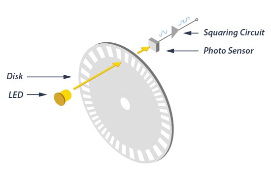
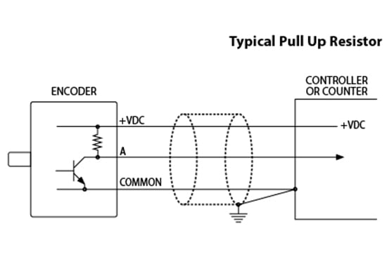
As seen in Figure 1, a beam of light emitted from an LED passes through a transparent disk patterned with opaque lines The light beam is picked up by a photodiode array, also known as a photosensor. The photosensor responds to the light beam, producing a sinusoidal wave form, which is transformed into a square wave or pulse train. This pulse signal is then sent to the counter or controller, which will then send the signal to produce the desired function.

Figure 1 diagrams a typical rotary encoder. Incremental encoders can provide a once-per-revolution pulse (often called the index, marker, or reference) that occurs at the same mechanical point of the encoder shaft revolution. This pulse is on a separate output channel (Z) from the signal channel or quadrature outputs. The index pulse is often used to position motion control applications to a known mechanical reference.

Resolution

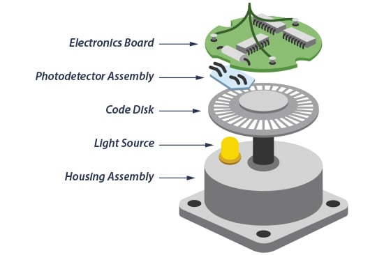
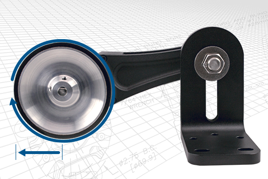
Resolution is a term used to describe the Cycles Per Revolution (CPR) for incremental encoders. Each incremental encoder has a defined number of cycles that are generated for each 360 degree revolution of the shaft. These cycles are monitored by a counter or motion controller and converted to counts for position or velocity control. Figure 2, at right, shows how the whole encoder comes together.


wp2011_parts-of-rotary-encoder_760x507

Figure 2

Application Example

Figure 3 shows one example of how an encoder is used in a typical motion control application. Cut-to-length, plotters, packaging and conveying, automation and sorting, filling, imaging, and robotics are all examples of applications that would use an encoder. The process is the same: a count is generated by the encoder and sent to the controller, which then sends a signal to the machine to perform a function.

wp2011_cut-to-length-application-example_1080x608

Figure 3

Conclusion

For more information about how an encoder works, watch this Encoder 101 video, “What’s an Encoder?" And if you still have questions about how an encoder would work in your specific application, or anything else encoder-related, give us a call. When you contact EPC, you talk to real engineers and encoder experts who can answer your toughest encoder questions. Contact EPC today to get the information you need.

downloadDownload the PDF

How an Encoder Works


More Resources