wp_header-bg_circuit-board_1920x1080
White Paper | WP-2000

Selecting Digital Encoder Outputs

Executive Summary

The output type for an encoder is an important consideration when specifying an encoder for a motion control application. The first consideration is the number of output channels, and the second consideration is the receiving device.

Encoder - A Definition

An encoder is an electro-mechanical device that translates mechanical motion into electrical signals. There are two major types of encoders: linear encoders and rotary encoders.

Linear encoders have a read head and track. The read head will slide along the track with a predetermined scale. This will produce an output for distance traveled typically in pulses per inch (PPI).

A rotary encoder converts the angular movement of a rotational device and will have an output for rotation about the fixed axis, typically in cycles per revolution (CPR). Figure 1 shows two typical motion feedback systems where rotary encoders are used.

wp2000_feedback-loop-graphic-updated_760x507

Figure 1. Two types of feedback systems. Closed-loop feedback is where the encoder signals control the motor without any user inputs. Open loop feedback is where the encoder signal runs to a display and the user adjusts the motor to fit a desired output.

Encoder Types

Within linear or rotary encoders, there are two basic types of electrical output formats: incremental or absolute. Absolute encoders have a unique digitally coded output, or address, for every distinct position of the encoder. Incremental encoders will output a count or pulse at periodic predetermined intervals.

Rotary incremental encoders are the most commonly used encoder. We will focus on rotary incremental encoders for this discussion.

There are two important considerations when selecting the outputs of an encoder. The first is the number of output channels. The second is the electrical output characteristics of the encoder channels. In order to make this determination, it is very important to understand the requirements of the receiving device.

Receiving devices may consist of PLCs, motion controllers, high speed counters, or any other device designed to accept encoder inputs. Some receiving devices have selectable inputs, which will provide more flexibility in selecting the appropriate encoder.

Output Channels

Rotary incremental encoders have three basic choices for the number of channels:

  • Single channel (Figure 2)
  • Two channels in quadrature, often referred to as a quadrature encoder (Figure 3)
  • Quadrature with an index channel (Figure 4)

Single Channel

As seen in Figure 2, a single channel has a single “A” channel that will output a set number of pulses per revolution. The single channel encoder will give feedback that can determine rate, velocity, or acceleration. A single channel encoder cannot give directional feedback and is therefore limited from many bi-directional applications.

Quadrature

A quadrature encoder (see Figure 3) has two channels, typically referred to as channel A and channel B. Each channel of the quadrature encoder will have the same number of pulses per revolution offset by 90º electrical. A standard Accu-Coder® encoder will have channel “A” lead channel “B” for clockwise shaft rotation. This quadrature relationship provides directional information to the receiving device. Many receiving devices also have the capability of using a quadrature encoder’s signals to perform edge counting to increase the resolution two or four times, sometimes called quadrature counting. This can increase the effective system resolution by up to four times.

Quadrature with Index

The index or “Z” channel of an encoder happens once per revolution of the encoder (see Figure 4). The index is also sometimes called a reference, marker, or homing pulse. One common function of the index is as a home position locator. Every time the index is triggered, the receiving device knows where the encoder is within its rotation. The index is normally 180º electrical and gated to either channel A or channel B. In addition to standard gating, Accu-Coder® encoders have other gating options that a customer can order based on the customer’s special needs.

Some rotary incremental encoders have additional auxiliary channels for motor commutation. Encoder commutation channels can replace Hall Effect sensors in a brushless DC motor for motor control and timing. The pole count of the encoder commutation tracks needs to match the motor pole count. Encoder commutation for DC motors is more accurate and repeatable than using Hall Effect sensors. The typical encoder commutation accuracy is ±1º mechanical. The higher accuracy commutation outputs will allow the motor to run more efficiently.

After selecting the correct number of channels for an encoder, the next task is selecting the electrical output type of the encoder channels. There are multiple output types to choose from, each with its own advantages and disadvantages. The four most common output types are: differential line driver, push-pull, open collector, and pull-up.

wp2002_figure2_single-channel-output

Figure 2. Single channel encoder output

wp2000_figure3_quadrature-encoder-counting

Figure 3. Quadrature encoder and quadrature counting

wp2002_figure4_quadrature-encoder-with-index-channel

Figure 4. Quadrature encoder with an index channel


Electrical Output

There are four major types of electrical output:

Differential Line Driver

With differential signals, there will be two connections for each channel (see Figure 5). It provides differential output, or complementary signals for noise immunity. Noise immunity is obtained by what is called “common mode rejection,” which occurs when noise is present on a differential pair, and the differential receiver cancels the noise. Differential line driver is the preferred output type for longer encoder cable lengths because of the inherent noise immunity. Differential line driver also meets RS-422 standards when operated at 5 VDC. An encoder should have differential line drive outputs when the receiving device is set up to receive differential signals. Some Accu-Coder® encoders also have a 5 VDC regulated differential line driver output. This will take a higher input voltage and regulate the output to 5 VDC.

Push-Pull

Push-pull is sometimes referred to as a “totem-pole” type of output circuit. This is a combination of sinking and sourcing outputs. When the output is in logic state high, current will source to the receiving device load. When the output is in logic state low, current will sink from the load.

Push-pull does not have the noise immunity that is inherent in a differential line driver. When the output is high, the noise on the DC power supply (ripple, voltage, spikes, etc.) may show up on the output of the encoder. A push-pull output type can replace a PNP transistor output in some applications. Some encoders have a 5 volt regulated push-pull output, so the encoder will have a 5 volt signal when the supply voltage to the encoder is higher than 5 volts.

NPN Open Collector

NPN open collector is a current sinking output type and requires a pull-up resistor external to the encoder. Typically, the pull-up resistor is built into the receiving device.

Open collector is useful for doing what is called level shifting. Level shifting occurs when the encoder is pulled up externally to a different voltage level. For example, the encoder can be powered with 5 volts, and the output can be pulled up to a 24 VDC level. Encoder Products Company offers an open collector differential output on some encoder models. This is an open collector output with the complimentary channels similar to a line driver.

It should be noted that NPN open collector is not the same as a PNP output. A PNP output requires a pull down resistor and is a current sourcing type output. PNP outputs are seldom used in encoders.
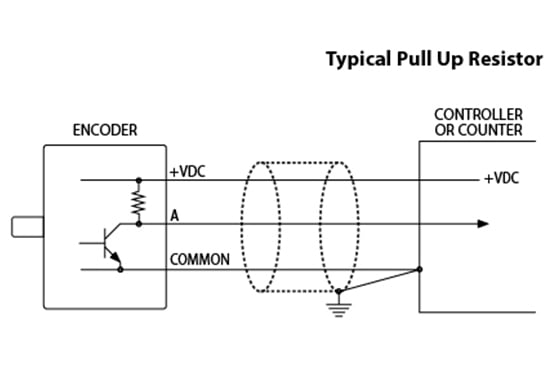
Pull-Up

Pull-up is the same as the open collector, but, as the name implies, it contains the pull-up resistor internal to the encoder. This is useful for customers who do not need the level shifting capabilities of an open collector and do not want to add external pull-up resistors to the feedback system. Common values for the internal pull-up resistor in an EPC Accu-Coder® encoder are between 1.5k and 2.2k.


wp2002_figure5_differential-outputs

Figure 5. Differential outputs


Conclusion

Choosing the correct number of channels and the correct output type for an encoder can be the determining factor in whether or not a feedback system will function properly. This is one of the most common problems customers have when selecting encoders. It is vital to remember that it is the receiving device that determines the correct configuration of the encoder’s outputs. If the encoder configuration is in question, contact EPC for assistance.

If you still have questions about output, or anything else encoder-related, give us a call. When you contact EPC, you talk to real engineers and encoder experts who can answer your toughest encoder questions. Contact EPC today to get the information you need.

downloadDownload the PDF

Selecting Digital Outputs


More Resources