Choosing the correct number of channels and the correct output type for an encoder can be the determining factor in whether or not a feedback system functions properly. There are four common output types to select from, and most of EPC’s encoder models can be ordered with any of these four types. There are also some speciality output types, available on select models.
Determining What Output Type Your Application Needs
The receiving device determines the correct configuration of the encoder’s outputs. One type of output is not necessarily better than another; it depends on the individual application and the controller being used with the encoder. For instance, if the controller calls for “compatible NPN” output circuitry, a simple open-collector output type is the right choice. The circuit will be current sinking, and the load on the controller side will pull up the encoder output to the desired voltage. In another example, if the controller is set up to receive differential signals, for better noise immunity (especially at higher voltages), use an encoder with an HV differential line driver output. Reference your controller’s manual for specific information on its requirements, and of course, EPC Technical Services is here to help if you still have questions.
Common Output Types
1. “OC” NPN Open-Collector
“OC” NPN Open-Collectoris a current sinking output and is useful for doing what is called level shifting. This is when the encoder is powered with one voltage level, and the output is pulled up externally to a different voltage level. For example, the encoder can be powered with 5 volts DC and the output can be pulled up to a 24 volt DC level.
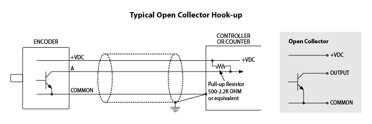
NPN electrical hook-up (left) and OC output circuit (right).
2. “PU” Pull-Up
“PU” Pull-Up is the same as the open-collector, but, as the name implies, it also contains an internal pull-up resistor to the positive supply voltage supplied to the encoder. (Not to be confused with a “sourcing” type output.) The amount of current that can be sourced with the output transistor in the off state is limited by the supply voltage and the value of the internal pull-up resistor. Common values for the internal pull-up resistor used in encoder is between 1,500 and 2,200 Ω. This type of output is used when the counter, or PLC does not have built-in provisions to pull up the input circuitry.
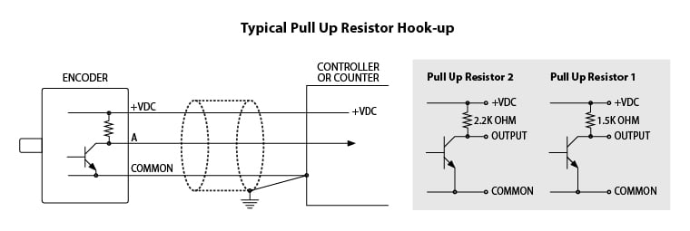
PU electrical hook-up (left) and PU output circuit (right).
3. “PP” Push-Pull
“PP” Push-Pull is sometimes referred to as a “totem-pole” type of output circuit. For our discussion here, we will treat them equally. This is a combination of sinking and sourcing outputs. When the output is in the logic high state, current is sourced to the load. When the output is in the logic low state, current is sinked from the load. It suffers from lack of noise immunity, however, because when the output is high (sourcing) whatever noise, ripple, etc., that is on the DC supply lines to the encoder is directly dumped into the input circuitry of the counter, PLC, or whatever the load. When the output is sinking (low state), the noise immunity is the same as if the open-collector was used.
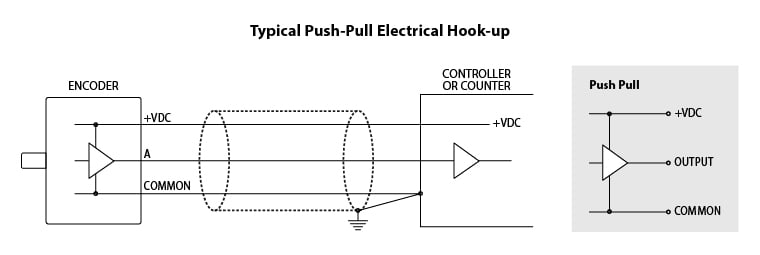
PP electrical hook-up (left) and PP output circuit (right).
4. “HV” Differential Line Driver
“HV” Differential Line Driver provides differential outputs, or complementary signals for noise immunity. It meets RS-422 standards when operated at 5 volts DC. This type of output should be selected if the load device is set up to receive differential signals. The output lines are electrically balanced and if the proper balance between them is not maintained, ringing and spurious oscillations can occur on the lines. At higher frequencies it may cause false counting in the load device. Noise immunity is obtained by the nature of what is called “common mode” rejection. (For more information, see white paper WP-2004: Noise & Signal Considerations.) Remember that for each output channel the encoder has, one additional wire in the cable must be used for the complement signal. Also, for applications where there will be long lengths of interconnecting cable, which can degrade the signal, HV is the best option to ensure a clear signal.
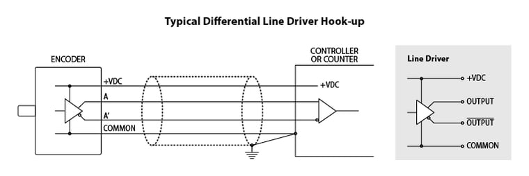
HV electrical hook-up (left) and HV output circuit (right).
Specialty Output Types
The following output types are available on select EPC encoder models:
“OD” Open Collector/Differential:
An open collector output with complimentary channels similar to a line driver.
“LO” Line Driver on ABZ and Open Collector on UVW:
Complimentary line drivers outputs for the clock channels A, B, and Z. Open collector outputs for the commutation channels U, V, W.
“H5” Line Driver at +5VDC:
Regardless of the input voltage, the outputs will be limited to +5VDC complimentary line driver. Input voltage is limited to 8-28 VDC for Models 702, 725, 758, 802, and 755.
“P5” Push-Pull at +5VDC:
Regardless of the input voltage, the outputs will be limited to +5VDC Push-Pull.
Other Common Industry Terminology
Output types are also referred to in the industry as “HTL”, “TTL”, “PNP”, and many others. Sometimes the output IC (7272, 4469, 8830, 7406, 3904, 26LS31, etc.) is all that is used to define the output type.
Download the PDF

Contact EPC
If the output type you need is not discussed here or is otherwise unclear, or if you have any additional questions, please contact EPC Technical Service at 800-366-5412 or email sales@encoder.com.
TB-109 Rev D, 11/03/2017
